Home Temperature Monitoring
The story is about how I built a homebrew temperature/humidity monitoring system using Arduino, XBee, and Raspberry Pi.
Part 1. Abstract
The main idea is to build a system to monitor temperature and humidity in my house and have access from a phone, tablet, laptop, etc. Additionally, I want to have historical data and show temperature, and humidity charts for the last 24 hours, month, and year, for instance.
To build the monitoring system I’m going to use Arduino Pro Mini as the main device which will read data from DHT22 temperature/humidity sensor and send them by Digi ZigBee Series 1. As a receiving device, I will use Raspberry Pi 3 with connected Digi ZigBee Series 1 but configured as the receiver.
All code is available on GitHub, feel free to fork and use the code.
Let’s get started.
Part 2. Building Sending Device
In this section I’m going to go through the steps I did to create a device that will get temperature, and humidity data from the DHT22 sensor and send it to a receiver, see Part 3. Building Receiving Device section.
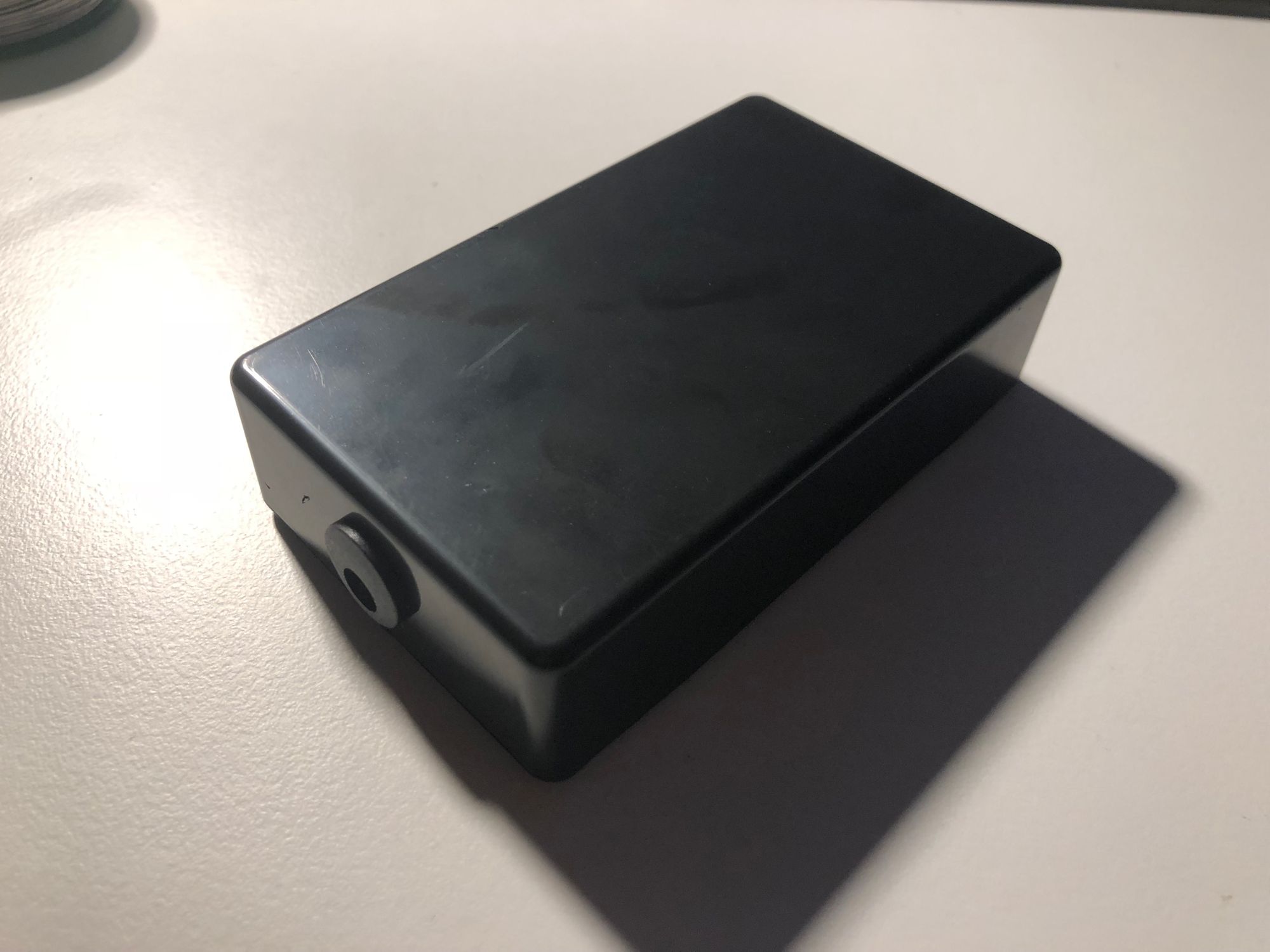
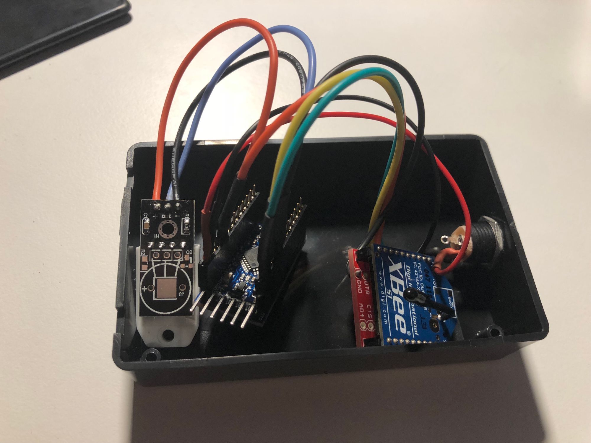
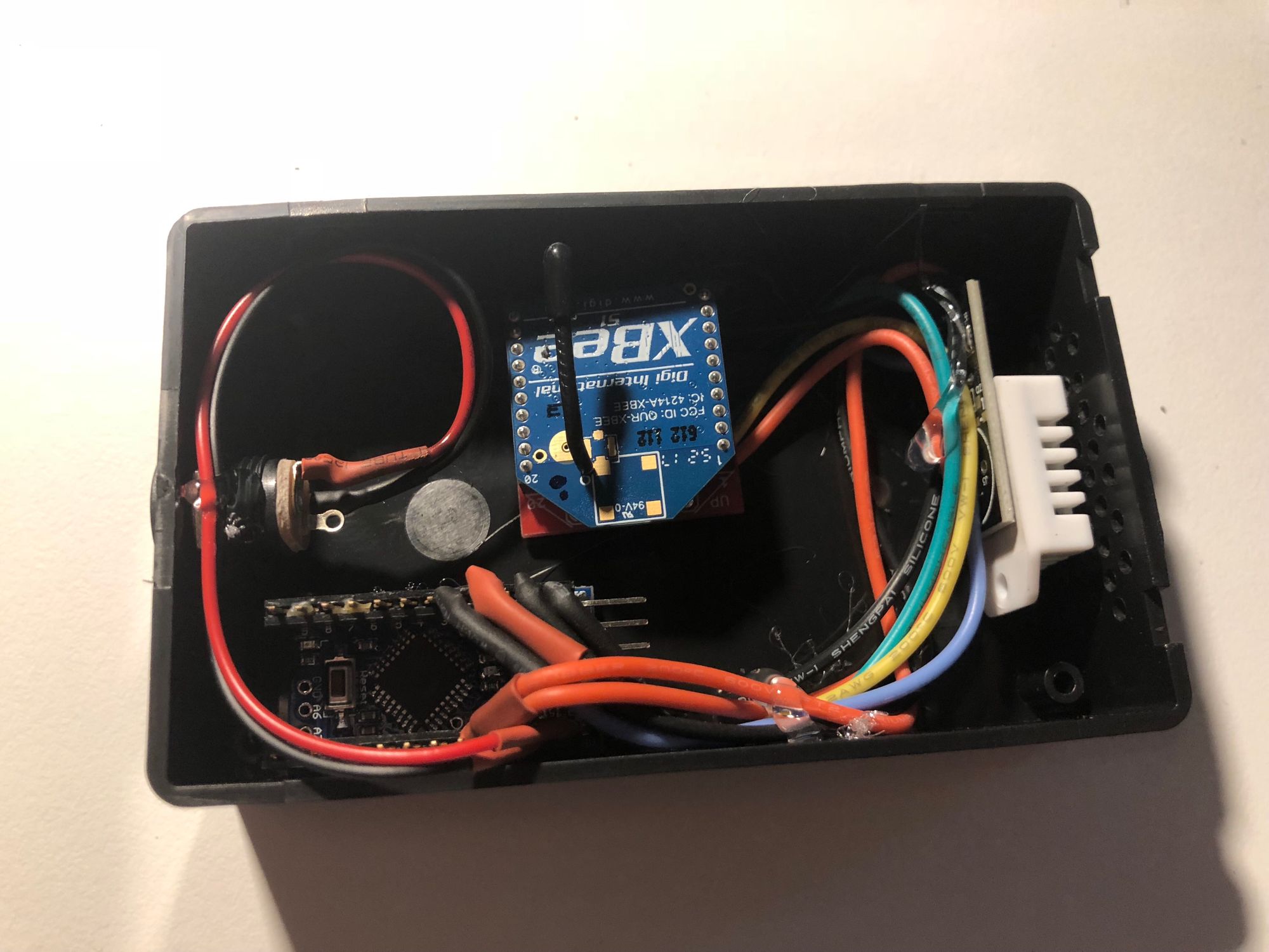
The final device looks as in the images below:
Part 2.1. Configuring XBee
Each XBee device must be configured to communicate with another XBee device, also please note that here I use XBee Series 1, see some details in the following posts XBee Series 1 vs. Series 2, XBee Buying Guide.
For the configuration, I used XCTU - which allows you to configure XBee modules and see received data sent by other XBee modules if you would like to debug how XBee module configuration works. To connect the XBee module via USB I used Waveshare XBee USB Adapter.
You could follow the following steps to set up XBee modules:
In XCTU click on Add device to add USB connected XBee module
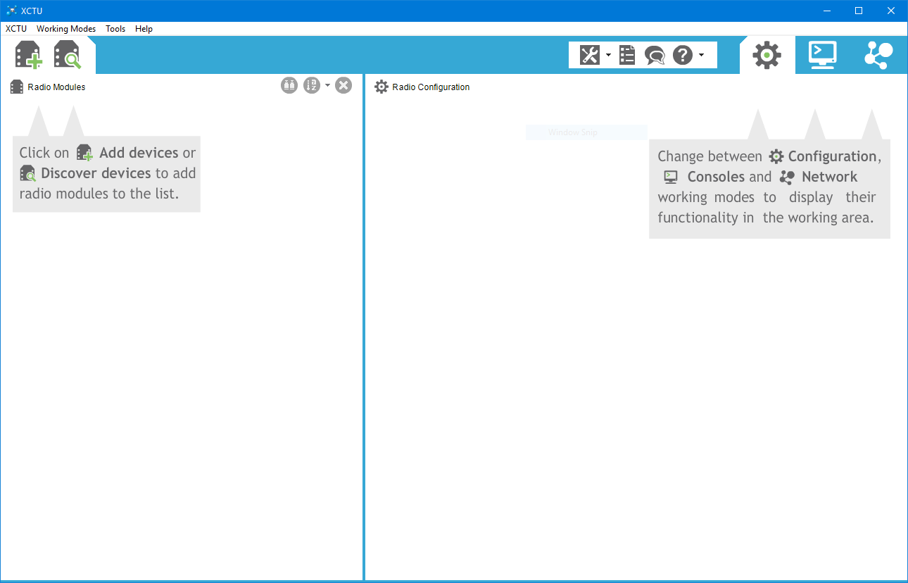 XCTU Main Screen
Select the connected device, as on the screenshot below.
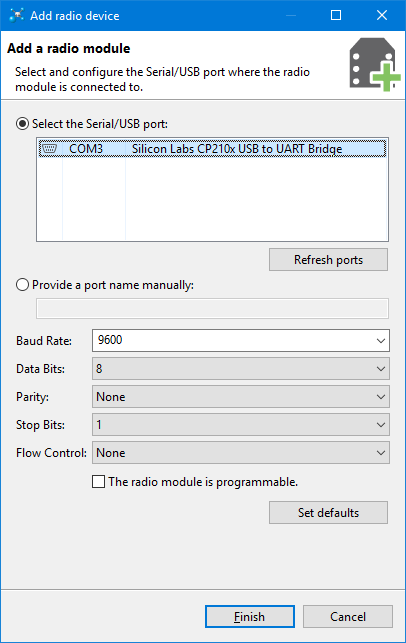 Add module dialog
Note: if you don’t see your XBee module, make sure you have installed a driver. If you use Windows you could see the connected device in the Device Manager. I had such an issue and after installing that particular driver, the issue has been resolved.
After that, you will see the connected XBee module in the list of modules
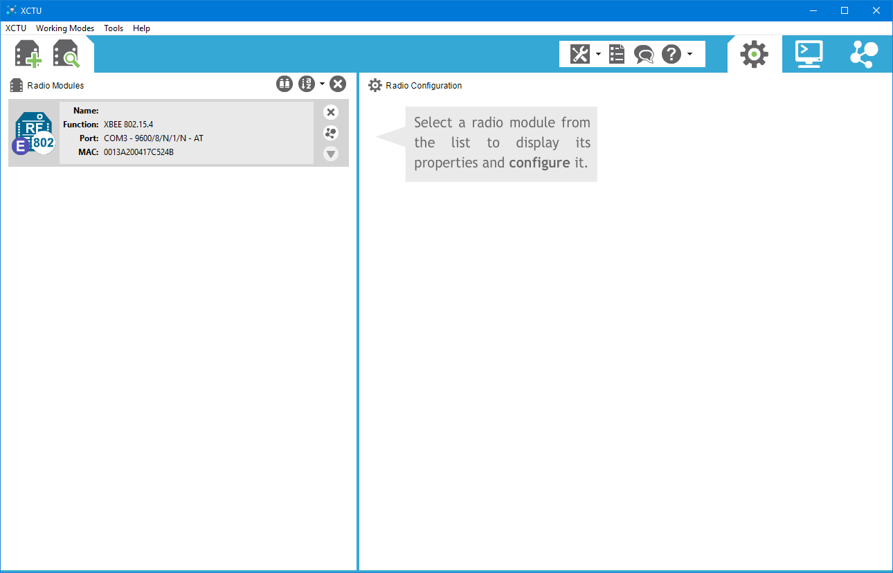 Connected XBee
3. Select the module and update: ID, DL, and MY values.
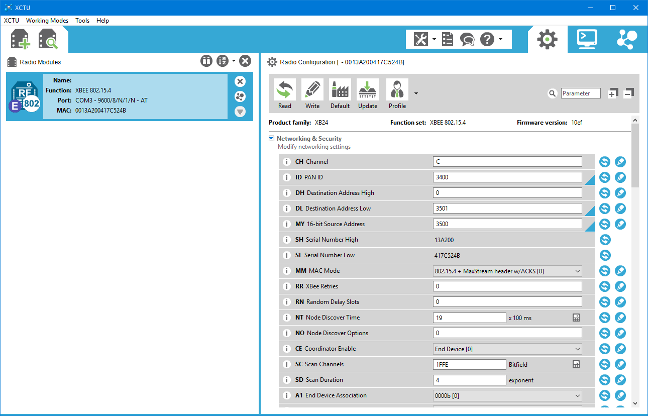
Here is what I used for my configuration:
| Device | ID PAN ID | DL Destination Address Low | MY 16-bit Source Address |
|---|---|---|---|
| Receiver | 3400 | 3501 | 3500 |
| Sender 1 | 3400 | 3500 | 3501 |
| Sender 2 | 3400 | 3500 | 3502 |
| Sender 3 | 3400 | 3500 | 3503 |
PAN ID must be the same for all devices, DL for Sender [x]’s is 3500 as the Receiver’s MY 16-bit Source Address value. Senders MY 16-bit Source Address just unique IDs.
After these steps, XBee modules are ready for the next steps.
Useful links:
Part 2.2. Configuring Arduino
DHT22 and Digi ZigBee Series 1 need to be connected to Arduino Pro Mini before uploading the code. See the schema below how I connected Arduino Pro Mini with DHT22 and Digi ZigBee Series 1:
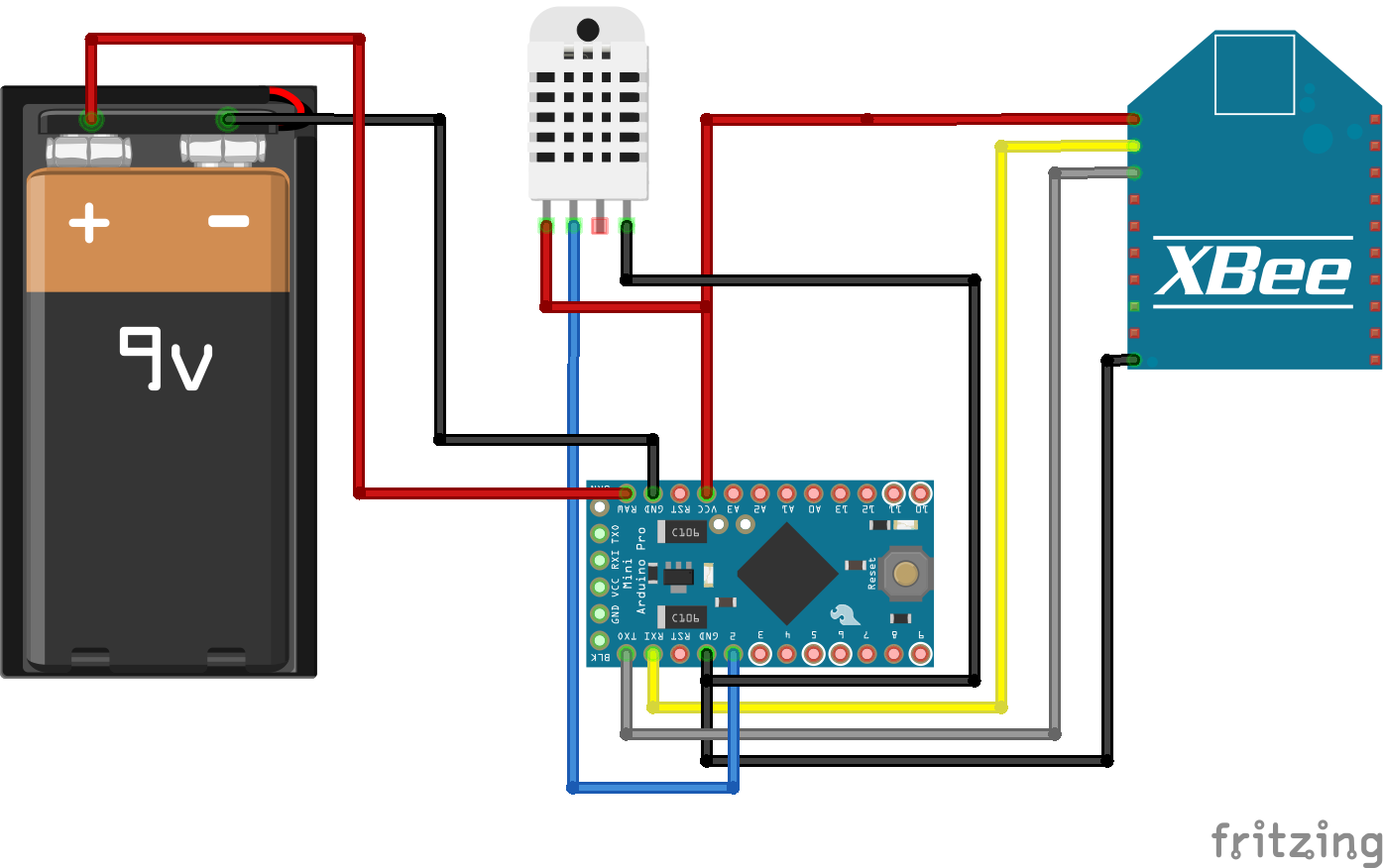 Sketch
Arduino Pro Mini pinout is available here.
I used an additional Breakout Board for XBee Module with Generic 2mm 10 Pin XBee Socket Header to connect Digi ZigBee Series 1.
When everything is connected code can be uploaded to the Arduino Pro Mini. Arduino Pro Mini doesn’t have a USB port you need to use FTDI device, I used SparkFun FTDI Basic Breakout - 3.3V.
Please note: that I used 3.3V Arduino Pro Mini and therefore you have to use 3.3V FTDI.
Arduino sketch file is available here - Monitoring.Sender.ino, you just need to provide a unique DEVICE_ID for your device, e.g. GUID in line #4 of the sketch file and upload to Arduino Pro Mini.
Probably when you upload the code into your Arduino you will need to disconnect the XBee module, otherwise, you will get an error in the Arduino IDE.
Part 3. Building Receiving Device
Part 3.1. Configuring Raspberry Pi
Before running any code on Raspberry Pi, you need to connect Digi ZigBee Series 1. In my case, I used the XBee USB Adapter for it.
Now you are ready to upload the code into your Raspberry Pi. The easiest way is to use SSH. In this post, I’m not going to describe how to install Raspbian and configure SSH, but you could easily google it.
Software for the Raspberry Pi(receiver) consist from two parts:
- A Python script which reads data from the USB connected XBee module and calls Web API to send received data;
- A Web part consists from an API and UI
- the API:
- receives requests from the Python script and save into MariaDB
- retrieve data for the UI SPA application
- the UI is the Angular application:
- shows connected devices and theirs temperature, humidity, and head index;
- shows historical data for each particular device using charts
- the API:
To build and deploy the code to the Raspberry Pi use scripts from the scripts directory: build.sh to build API and UI, deploy.sh to deploy(don’t forget to update the IP address in the deploy.sh script).
You could call sh ./build.sh && sh ./deploy.sh from the scripts directory to build and deploy.
Prerequisites to run the code on the Raspberry Pi:
- Python 3 must be installed;
- .NET Core must be install, see Link #4 in the Links section.
After deployment, the code connects to your Raspberry Pi, navigates to the monitoring directory and call nohup sh ./run.sh & to leave run.sh the script running when you close SSH connection.
Part 4. Result
The final result is a Web Application that looks like
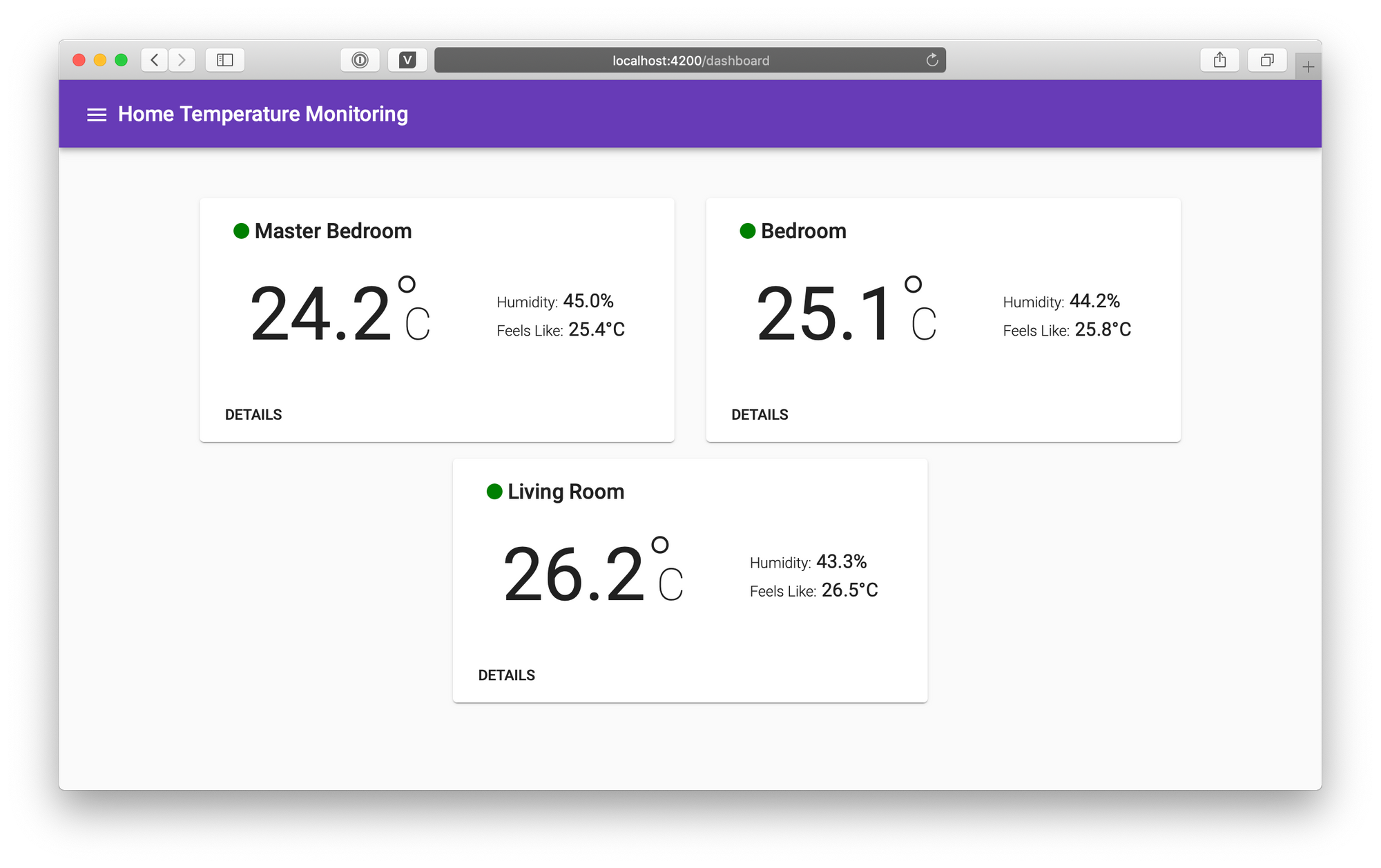 Main screen.
Feel free to ask me any questions.